|
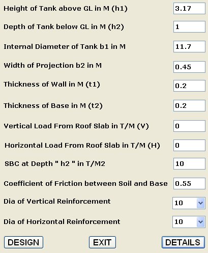
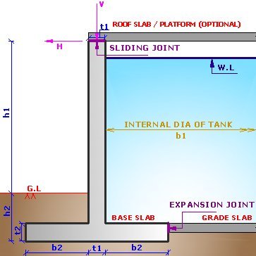
DESIGN OF CIRCULAR WATER TANK CLOSE OR OPEN FROM TOP RESTING ON GROUND |
|
|
|
|
|
DESIGN RESULT |
| DESIGN OF CIRCULAR WATER TANK RESTING ON GROUND Height of Tank above GL in M (h1): 3.17 Depth of Tank below GL in M (h2): 1 Internal Diameter of Tank b1 in M: 11.7 Width of Projection b2 in M: 0.45 Thickness of Wall in M (t1): 0.2 Thickness of Base in M (t2): 0.2 Vertical Load From Roof Slab in T/M (V): 0 Horizontal Load From Roof Slab in T/M (H): 0 SBC at Depth " h2 " in T/M2: 10 Coefficient of Friction between Soil and Base: 0.55 Dia of Vertical Reinforcement: 10 Dia of Horizontal Reinforcement: 10 Concrete Grade: M30 Steel Strength (fy) [N/MM2]: 415 ----------------------------------------------------------- H*H / (D*T) = 6.62 Hoop Tension in T / M at 1.32 M from Base = 15.75 Overturning Moment due to Lateral Water Force in T-M / M at Base = 1.16 Weight of Stem in Tons = 1.99 Weight of Base in Tons = 0.55 Weight of Water in Tons = 1.7865 Restoring Moment in T-M = 2.96 Total Vertical Load in Tons = 4.33 Base Eccentricity in M = 0.13 Maximum Pressure in Base in T/M2 = 6.73 Minimum Pressure in Base in T/M2 = 1.15 FOS against Overturning = 2.55 FOS against Sliding = 1.93 ----------------------------------------------------------- BM in Wall at Base Top in T-M = 1.16 Hoop Tension in Wall at Base Top in Tons = 15.75 Hoop Tension in Wall at 1.32 From Top in Tons = 7.87 Shear Force in Wall at Base Top in Tons = 2.63 ----------------------------------------------------------- Permissible Bending Tensile Stress in Wall in Kg/CM2 = 20 Actual Gross Bending Tensile Stress in Wall in Kg/CM2 = 16.39 Permissible Direct Tensile in Wall in Kg/CM2 = 15 Actual Hoop Stress in Wall in Kg/CM2 = 7.87 ----------------------------------------------------------- Capacity of Wall Sec. in BM in T-M = 4.05 Depth of Neural Axis for Wall in MM = 38.3 Vertical Wall Reinforcement near Base at Water Face in CM2/M = 7.05 Provide Vertical Wall bars near Base at Water Face as dia 10 MM @ 111 MM c/c Vertical Wall Steel at 1.99 M From Top at Water Face in CM2/M = 2.4 Provide Vertical Wall bars at 1.99 M From Top at Water Face as dia 10 MM @ 200 MM c/c Provide Vertical Wall bars Away from Water Face as dia 10 MM @ 200 MM c/c Horizontal Wall Hoop Reinforcement near Base at Each Water Face in CM2/M = 6.06 Provide Horizontal Wall Hoop bars near Base at Each Face as dia 10 MM @ 130 MM c/c Horizontal Wall Hoop Steel at 1.32 M From Top at Each Face in CM2/M = 3.03 Provide Wall Horizontal Hoop bars at 1.32 M From Top at Each Face as dia 10 MM @ 200 MM c/c ----------------------------------------------------------- Factored Shear Stress in Wall in Kg/CM2 = 2.63 Max. Permissible Shear Stress in Wall in Kg/CM2 = 36.7 Capacity of Wall Section in Shear in Tons = 4.9 ----------------------------------------------------------- Permissible Bending Tensile Stress in Base in Kg/CM2 = 20 Actual Gross Bending Tensile Stress in Base in Kg/CM2 = 17.38 ----------------------------------------------------------- Provide Transverse Tank Base bars at Each Face (T & B) as dia 10 MM @ 200 MM c/c Provide Horizontal Circular Tank Base bars at Each face as dia 10 MM @ 200 MM c/c ----------------------------------------------------------- Factored Shear Stress in Base in Kg/CM2 = 1.87 Max. Permissible Shear Stress in Base in Kg/CM2 = 36.7 Capacity of Base Section in Shear in Tons = 3.8 ----------------------------------------------------------- Total Concrete Quantity Consumed by Wall + Base in M3 = 55.53 Total Steel Quantity Consumed by Wall + Base in Kg = 3197.6 Clear Cover to Reinforcement is taken as 40 MM : Load Factor = 1.5 For Expansion and Construction Joint details refer Standards. Design Roof Slab (If reqd.) as per IS 456. Use Minimum M30 Grade Conc. The Applied Unbalance Load { H } if any shown on Top is from Roof Slab / Platform. Sliding Joint in Steel Platform can be provided by providing Slotted holes in Beams. Water Table is assumed to be absent or beyond h2. Top of Tank is assumed as free / provide sliding joint. Provide minimum Grade Slab thickness of 150 MM. If Tank Diameter is < = 15 M. then provide reinforcements as Tor 8 @ 135 c/c near the top surface of grade Slab. If Minimum Tank Diameter is > 15 M. then provide reinforcements as Tor 10 @ 135 c/c near the top surface of grade Slab. ooooooooooooooooooo fini oooooooooooooooooooooooo |
|
|