| LEARN COMPOSITE STEP BY STEP | |
|
STEP NO. 10 Beam Design, Quantities, Cost Estimation and Column Loads |
|
 |
|
 |
After entering Data & Checking
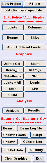
it thoroughly, Relax, let the software do its Job. The 1st milestone is Analysis. When Program starts, the Menu above is displayed. Under the Beam + Column Design + QTY Heading following options are displayed. ● Beam ● Beam Log File ● Column Loads ● Script ● Column ● Column Log ● Standard Details ● Quantities Now Click on " Beam " Option. Following Graphics is displayed. |
 |
|
|
|
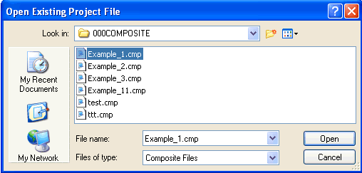
Now select " Example _1 File & Press Open
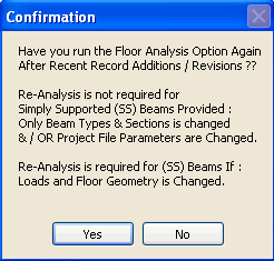
Button. Following Warning is displayed. |
 |
|
|
|
This is a very Important
Message. In case a user has edited or added any Joint / Column / Beam or Slab
Member after performing analysis then he should re-perform the analysis, else
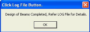
old (in-correct) results will be displayed. However Re-Analysis is not required for Beams Provided: ● Only Beam Type & Section is Changed. ● Project File Parameters are Changed. Re-Analysis is required for Beams if Loads & Floor Geometry is Changed. Click " Yes " if you have not revised any member after analysis or click " No " if you are not sure. If " Yes " is clicked then following message will be displayed. |
 |
|
|
|
Now Click the " Log File "
Button.
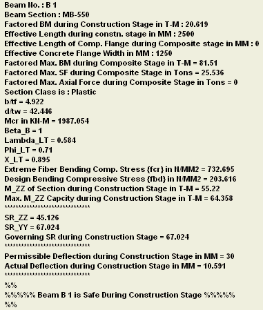
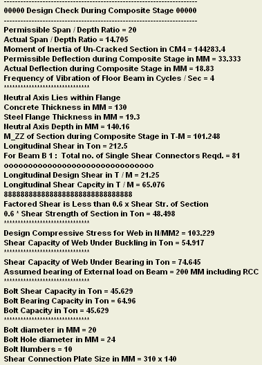
Following Design Results (Part) is displayed. The LOG file will display Beam
results (Safe / Unsafe) & various parameters on which Beam is evaluated. User
should study the each parameter in order to redesign the beam for safety or for
economy / Optimization. The Composite Beam Design is carried out as per following Codes,  Construction Stage: As
per IS 800 :
2007.
Composite Stage: Construction Stage: As
per IS 800 :
2007.
Composite Stage:(a) Section Classification and BM as per Euro 4. (b) SF, Axial Load, Deflection, Slenderness, Bolt, Weld Design as per IS 800 : 2007.
Profile
Deck design by Deck manufacturer. |
|
|
|
|
|
|
|
|
Note that Step by Step design is given for Construction & Composite stage. If Beam is Unsafe, all the parameters will be displayed indicating why beam is unsafe. A designer shall study & correct the various parameters such as Concrete Grade/ Concrete thickness, Profile Depth / Thickness and Beam Size. |
|
|
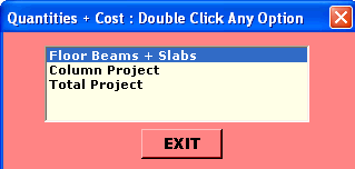
Now Click " Quantity " Option. Following Graphics is displayed. |
 |
|
|
|
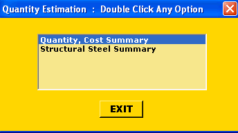
Now Double Click " Floor Beams + Slabs " Option. Following Graphics is displayed. (Quantities and Cost of Column Project and Total Project will be discussed in later Steps). |
 |
|
|
|
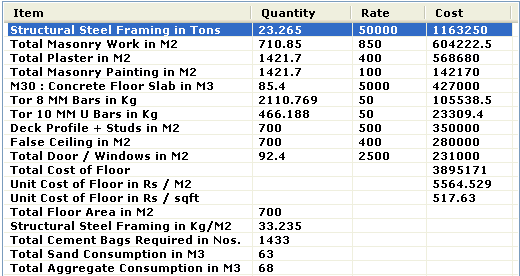
Now Double Click " Quantity, Cost Summary " Option. Following Graphics is displayed. |
| DISPLAYING QUANTITIES AND COST SUMMARY | |
 |
|
|
|
The above display gives cost
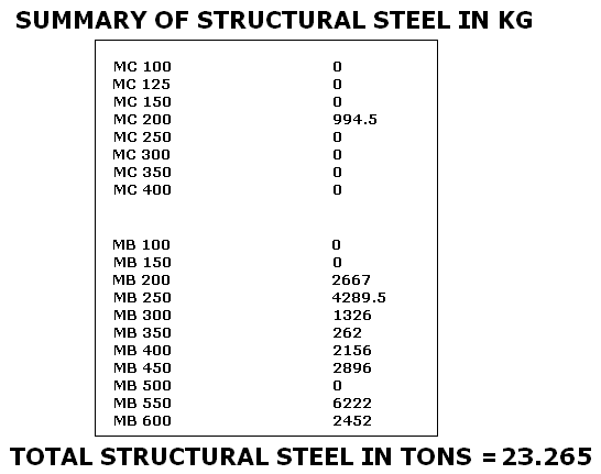
summary as per the Rates Put-In during creation of Project File. Now Double Click " Structural Steel Summary " Option. Following Graphics is displayed. |
 |
|
|
|
Note that the above steel weight
does not include end connections & member splice. We have taken C/C distance
between columns as member length, which may offset the connection + splice
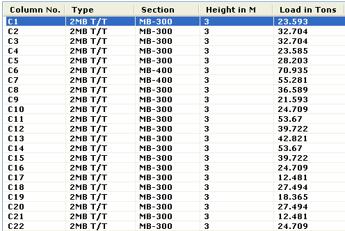
weight. Now Double Click " Column Loads " Option from the Main Menu. Following Graphics is displayed. |
|
UN-FACTORED COLUMN LOADS PART DISPLAY |
|
 |
|
|
|
The above Column Loads Graphics
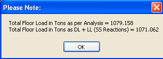
is self explanatory. Self Weight of Column is not included. When " OK " button is clicked following vital Statistical Check is displayed. The Difference should not exceed say 10 %. The major difference should calls for closer look at the Data-Input. |
 |
|
|
|
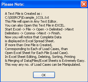
When " OK " button is clicked, following Important Message is displayed. |
 |
|
|
|
The above message describes how
any number of Load Cases can be Run & Manipulated once the File is Exported to
Excel Spread Sheet. Note the File Name Carefully. Click " OK " button. Now we have come to the end of Step # 10. Let us proceed to Step No. 11. |
| STEP NO. 10 IS OVER. |
|


|
|